Rock masses and software
For the rock masses complex formations, geotechnical characterization and modeling is necessary to evaluate the characteristic resistance: the nature, geometry and resistance of discontinuities are important. In addition, it must be specified whether the characteristic resistance refers to discontinuities or to the rock mass. In this respect, we want to give a more in-depth explanation by tackling geological and geotechnical issues and aspects.
Rock mass and discontinuities
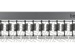
Rock masses on the earth’s surface show, in the majority of cases, discontinuities or weak surfaces that inflluence mechanical behavior. These discontinuities identify blocks of rock mass material (or intact rock); Fig.1. In particular, discontinuity means any interruption of continuity in a rock mass having low or no tensile strenght (cracks, stratification planes, schistosity planes, faults, alteration discontinuities, etc.; ISRM, 1978). Therefore, for a stability of a rocky slope or an exavation front of hard rock it is necessary to identify and study both the structure of the rock mass and the nature of the discontinuities. In fact, the definition of a geomechanical model must be able to know and predict the behavior of the rocky materials due to the application of the endogenous and exogenous forces exerted on them and it is necessary to define for each hypothetical kinematic mechanism the forces acting and resistant to counteract the gravitational instability (Gonzalez de Vallejo, 2005).

Fig. 1. Outcrop of Calcarenite from Belvedere M.mo (CS), Italy.
Strength
As previously seen, the rock matrix is considered intact rock and therefore without discontinuity but in nature has heterogeneous and anisotropic behavior linked to its mineralogical structure (e.g. stratification, foliation, cleavage, schistosity). Therefore, it is essential that both the structure of the rock mass and the discontinuities are described also considering the petrographic aspect. Furthermore, as the discontinuity surfaces constitute weaknesses that regulate the mechanical behavior of the rock masses by conditioning the strength of the complex, the mechanisms, the deformation and breakage areas, it is possible to affirm that the strength of a rock mass decreases with increasing number of discontinuities (Gonzalez de Vallejo, 2005). Therefore, to examine the ability of a rock mass to oppose the destabilizing forces it is necessary to distinguish and define: a) the strength of the rock matrix; b) the strength of the discontinuities; c) the strength of the rock mass.
Intact rock strength
The strength of the rock matrix is determined in the laboratory by breaking a sample of the rock mass. Usable tests include: simple compression, Point Load Test, triaxial compression, straightforward direct traction. The purpose of the tests is to identify the strength of the specimens according to the effect of applied stresses and the intrinsic properties of the rock itself (mineralogy, grain size, porosity etc.). The failure criteria considered to calculate the strength of the material are that of Mohr-Coulomb and that of Hoek and Brown (1980). There are Geostru software such as RockLab, RockPlane which also consider these criteria for carrying out stability analysis and consolidation of the rock slopes; more details in par. Software.
When is the specimen strength value used?
During a stability analysis, the strength value obtained from the rock sample is used when it is representative of the whole rock mass. For example when the rock mass is not strongly conditioned by discontinuities due to the good quality of the rock or due to the reduced scale at which the analysis is carried out or, conversely, when the discontinuities are pervasive even at the sample scale (anisotropic rocks eg. shists).
The shear strength of discontinuities
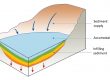
The shear strength of discontinuities can be determined by on-site or laboratory tests or can be estimated with the method proposed by the ISRM (1978, 1985, 1993) which is based on the geomechanical detection of the families of discontinuities characterizing the rock mass. The main geometric and mechanical parameters proposed to describe the discontinuity families are: orientation, spacing, continuity or persistence, roughness, strength to the walls of the joint, opening, filling, alteration, filtration, number of discontinuity systems, block sizes (Fig.2). Patton (1966) and Barton and Choubey (1977) are some of the criteria used for calculating the shear strength of discontinuities; these criteria are also used in some Geostru software such as RockMechanics.

Fig. 2 – Characteristics of discontinuities in rock masses: parameters describing the rock mass; from Wyllie (1999).
When is the discontinuity shear strength value used?
When we consider anisotropic rock masses with significant discontinuities. For example, the applications for which it is useful to evaluate the strength parameters of the discontinuities are 2D sliding and 3D sliding. In this regard, there are Geostru software (such as Georock2D, 3D, RockPlane) that allow to perform rockfall simulations according to various models thanks to which it is possible to design landslide protection works.
Rock mass strenght
When the rock mass is very fractured due to numerous discontinuity systems, for the calculation of the strength, the behavior of the entire rock mass is evaluated using methods that allow you to perform geomechanical classifications of the rock; methods that refer to the study of discontinuities; mathematical methods that evaluate the resistance of the rock mass by numerical modeling of a real phenomenon (back analysis). With regard to geomechanical classifications they provide quality indices and classes according to the parameter considered. Among the parameters considered in the most important classifications (e.g. Beniawski, 1976; Barton, 1979; Robertson, 1970; Sen and Kazi, 1984; Romana, 1988; Singh and Goel, 1999; Jasarevic and Kovacevic, 1996; also treated in the Geostru software RockMechanics) there are: compressive strength of the rock matrix (eg Point Load Test, Uniaxial Comp.Strenght), RQD (Rock Quality Designation), condition of discontinuities, orientation of joints, water conditions.
Evaluation of the stability of rock slopes and Stereographic analysis of structural geology
The reconstruction of a gravitational deformation model for a rock slope closer to real geological model allows to perform interpretations both on the possible kinematic mechanism and on the possible stabilization interventions: this can be done through stereographic representations of the discontinuities. In fact, since the structural structures of the joints present in a rocky front affect the possible kinematic mechanisms of breakage, it is important to analyze the families of discontinuities identified during the structural survey and for a simplified interpretation of these data, stereographic plots are used. In the verification of stability of rock slopes, the stereographic projections allow to have an appropriate representation of the spatial orientation data of the joints, layer planes, scisosity, faults etc., which characterize the rock mass studied. On these basis is possible to build the most realistic breaking model. The most frequent failure models, affecting the rock slopes are: planar failure (Fig.3a), wedge failure (Fig.3b), overturning (Fig.3b), rotational sliding (Fig.3d).

Fig. 3 – Main types of block failures in slopes, and structural geology conditions likely to cause these failures: (a) plane failure in rock containing persistent joints dipping out of the slope face, and striking parallel to the face; (b) wedge failure on two intersecting discontinuities; (c) toppling failure in strong rock containing discontinuities dipping steeply into the face; and (d) circular failure in rock fill, very weak rock or closely fractured rock with randomly oriented discontinuities. From Hoek and Bray, 1981.
The goal of the geological study of a rock slope is to build a geological model also aimed at understanding the evolutionary conditions that have produced the current structure with connected detailed analysis of the state and type of activity of any instabilities present. Therefore, particular attention must be paid: to the presence of specific structures that induce conditions of susceptibility to landslides; the presence and location of intercalations of less resistant lithotypes; stratigraphic or tectonic overlap of lithotypes with different lithological, hydrogeological and geostructural characteristics; the degree of alteration of the rock masses; the existence of discontinuities with high persistence and any filling material. In the area of interest, in the case of landslide phenomena, it is necessary to reconstruct the event in three dimensions (considering the data obtained from the investigation activities). For example, there are remote sensing techniques such as photogrammetry (Campbell and Wynne, 2011), laser scans (Gomarasca, 2009) that allow to reconstruct three-dimensional models of the slope with greater degree of detail.
Stabilization and monitoring
The choice of the type of intervention derives from a geotechnical characterization in this case of the rock mass. In relation to the type and objectives of the improvement and / or reinforcement intervention, the most appropriate experimental measures and investigations must be specified. Once the most suitable intervention for the case study has been carried out, if it may affect the functionality of the work in the project or of surrounding works, monitoring must be provided to evaluate the effectiveness of this intervention by controlling its behavior over time.
Software for a better characterization and geotechnical modeling
Considering the text described above, to better address the studies concerning the geotechnical aspects of the design and execution of works and interventions that interact with the rocks, the use of the following software is recommended:
- Rock falls 2D – GeoRock 2D: software for simulation of rockfalls using Lumped Mass and C.R.S.P. models;
- Rock falls 3D – GeoRock 3D: program for three dimensional analysis of rock fall and for the design and optimisation of protective works utilising a sophisticated algorithm for spatial analysis.
- Failure criterion of a rock mass according to Hoek-Brown – RockLab: Software for the determination of the failure criterion of a rock mass according to the model of Hoek-Brown (2002). The software also calculates the strength parameters of the rock mass, allows for the calculation of the bearing capacity of foundations on rock according to the methods of Carter e Kulhawy (1988); Serrano, Olalla e Gonzalez (2000).
- Analysis of rocky elements – RockPlane: is a software tool for the evaluation of localized instability rocky elements affected by seismic movements and/or by presence of water pressures within intersurface fractures.
- GeoMechanical Survey – G.M.S.: (GeoMechanical Survey) has the aim to represent and process the geo-structural survey of rock masses joints performed in-situ with the method of the compass and clinometer, according to the ISRM recommendations.
- Rock Mechanics: is a suite of 10 software for rock mechanics. It considers the geomechanical classification of: Barton, Bieniawki, Romana, Sen, Robertson, Sing & Goel, Jasarevic & Kovacevic. Stability analysis: Planar sliding, Three-dimensional sliding, Evaluation of the impact force of a rock, Prediction of the collapse phenomenon in the event of an earthquake.
Geostru 2020 news: Geoapp
Geostru company created a service available on the Geoapp web page where there are several applications for making online calculations. Geoapp includes over 40 applications for: Engineering, Geology, Geophysics, Hydrology and Hydraulics.
Among the applications present, a wide range can be used together with the software mentioned above, for example:
– Characterization of rock masses;
– Characterization of Barton;
– Slips along a plane;
– 3DWedge;
– Passive bar: nails;
– Rods;
– Anchored network systems;
– Rigid and elastic rockfall barriers;
– Stability analysis of flat surfaces.
References
Bieniawski Z.T. 1976. Rock mass classification in rock engineering. In Exploration for Rock Engineering, Proc. of the Symp., (ed. Z.T. Bieniawski) 1, 97-106. Cape Town, Balkema.
Campbell J. B. E Wynne R. H. (2011) – Introduction to remote sensing. Guilford Press.
Coulomb, C. A., 1776. Essai sur une application des regles des maximis et minimis a quelquels problemesde statique relatifs, a la architecture. Mem. Acad. Roy. Div. Sav., vol. 7, pp. 343–387.
Gomarasca M. A. (2009) – Basics of geomatics. Springer Science & Business Media.
González de Vallejo, L.I., Ferrer M., Ortuño and Oteo C., 2005 – Ingeniería Geológica. Pearson Prentice Hall.
Hoek, E. and Bray, J.W., 1981. Rock Slope Engineering. Revised 4th Edition, The Institution of Mining and Metallurgy, London, 341-351.
I.S.R.M. (1978) – Suggested methods for the quantitative description of discontinuities in rock masses. International Journal of Rock Mechanics and Mining Sciences & Geomechanics, Vol 15, pp. 319-368.
I.S.R.M. (1985) – Raccomandazioni ISRM per la misura della resistenza al punzonamento. Rivista Italiana di Geotecnica, 1, 151-197.
I.S.R.M. (1993) – Metodologie per la descrizione quantitativa delle discontinuità nelle masse rocciose. Rivista Italiana di Geotecnica, 2, 63-71.
ISRM, 1981 – Rock Characterization Testing and Monitoring. Brown, E., Ed., Pergamon Press, Oxford, 211 p.
Jašarević I., Kovačević M.S., 1996. Analyzing applicability of existing classification for hard – carbonate rock in Mediterranean area, EUROROCK ’96, Torino, pp. 811 – 818.
Patton, F.D. 1966. Multiple modes of shear failure in rock. Proc. 1st congr. Int. Soc. Rock Mech., Lisbon 1, 509-513.
Robertson A.M., 1988. Estimating weak rock strength, in: Sastry, K.V.S. (Ed.), Proceedings of the SME Annual meeting, Society of Mining Engineering, Phoenix, pp. 1-5.
Romana M., 1985. New adjustment ratings for application of Bieniawski classification to slopes, in: Proceedings of the International Symposium on the Role of Rock Mechanics in Excavations for Mining and Civil Works. International Society of Rock Mechanics, Zacatecas, pp. 49-53.
Sen Z. and Kazi A., 1984. Discontinuity spacing and RQD estimates from finite lenght scanlines. Int. J. Rock Mech. Min. Sci. And Geomech. Abstr., 21(4), 203-212.
Singh B., Göel R.K., 1999. Rock Mass Classification. A Practical Approach in Civil Engineering. Ámsterdam: Elsevier.
Wyllie, D. C. (1999) Foundations on Rock, 2nd edn, Taylor and Francis, London, UK, 401 pp.