


Description
The computation is based on the calculation of the rigid body equilibrium (EQU) of the infinitely rigid foundation (both flexural and extensionally) compared to the rotation around the sides (edges) of the base polygon on the lean concrete.
It is, therefore, to check if, concerning each side of the polygon, the ratio between the stabilizing moment and the overturning moment Mstab/Mdestab is higher than the partial safety factor ϒR = 1.15 (Eurocode). It is ultimately to make an equilibrium to the rotation around each of the sides, considering them as a linear fix hinge designing all the moments (overturning and stabilizing) in the vertical orthogonal plane to the individual base sides, excluding any of the ground reaction force (that in a limit state of rigid rotation in fact is free from contact with the spread footing).
GEOMETRY AND WEIGHT OF THE SPREAD FOOTING
The contact polygon of the spread footing can be assigned as Rectangular, Polygonal (up to 24 sides) inscribed in a circle of any generic radius, and Generic polygon (up to 24 sides). In the case of circular footing, simply assign a polygon of 24 sides to obtain a sufficient approximation. The height of the footing to be assigned refers to the vertical distance between the upper face on which are applied the concentrated loads (normal stress, moments and shears) transmitted from the superstructure (pillars, piles, wind towers, etc.) and the support horizontal footprint of the footing on the lean concrete. The footing can have a parallelepiped shape, both simple and stepped, provided that steps admit the same center of gravity in the plan of the base footprint (the total weight of the foundation must be calculated separately by the user, including any permanent overloads, and is always applied by the program in the centre of gravity of the base polygon). The weight of the footing is then reduced (automatically during the calculation) through partial coeff. ΥF = 0.9 as in Eurocode.
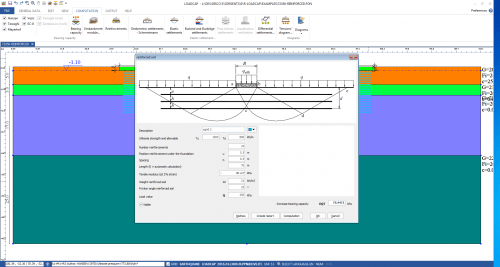
LOADS ACTING ON THE FOUNDATION UPPER FACE
The rigid body hypothesis allows to merge of all actions of the superstructure, not amplified, only in the stress components N, Mx, My, Vx, Vy (the positive moments are anti-clockwise relative to the axes x, y of reference and the shears are in the same direction as the axes themselves) and also allows you to apply these components into a single point of application, freely assigned by the user but chosen generally coincident with the centre of gravity of the superstructure attachment section with the upper face of the footing.
In the program must be therefore assigned the aforesaid loads and the coordinates of the application point that can be assigned directly by the user (via its coordinates) or be chosen coincident with the centre of gravity of the footing base polygon and in the latter case, is automatically calculated by the program.
For each side of the base polygon, the program automatically applies the coeff. ϒF = 0.9 to the normal force N (made up only of permanent loads; of the positive sign if directed downwards) and the coeff. ϒF = 1.5 to the remaining variable actions and performs the projection of the moment and shear components on the plane perpendicular to the side itself.
In the case of piles or wind towers, in general, the manufacturer only provides the resultant (with the sign always positive) on the upper face of the footing of the moments and shears unamplified by partial coeff. The box “Moments and shears from all directions” should be selected in this case. The calculation will ensure that for each side, the moment and shear projection will always correspond directly and simultaneously (in favour of safety) to the values assigned to Mx and Vy.
RESULTS
The software provides the overturning moment and the stabilizing moment relative to the footing base side to produce the lowest overturning safety coeff, between all sides. The verification will be positive if the said coefficient is not less than 1.15 regarding the Eurocode.


Reviews
There are no reviews yet.